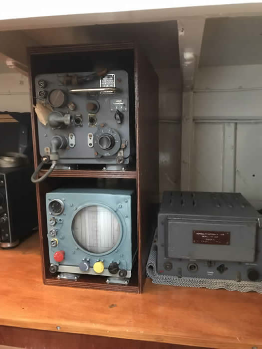
Medusa was equipped with the Gee navigator system (referred to by the navy as “QH”). The system was originally developed for precision bombing for the RAF and worked by measuring time intervals between pulses received from three locations. The receiver had plug-in tuning units and Medusa was provided with an RF27 tuning unit capable of receiving special frequency (XF) transmissions from the Southern GEE Chain. Special fine lattice charts covering the assault area were provided sealed, for security. They were not to be opened before receipt of code message “OPEN ONWEST/O”.
Medusa now has a working Gee system complete with a simulator for injecting signals. We believe, for D day, the system was in the chart room but we have installed the system in the wirelss office. There was so much extra equipment in the chart room that it was very cramped and extra ventilation was provided to take away the heat.
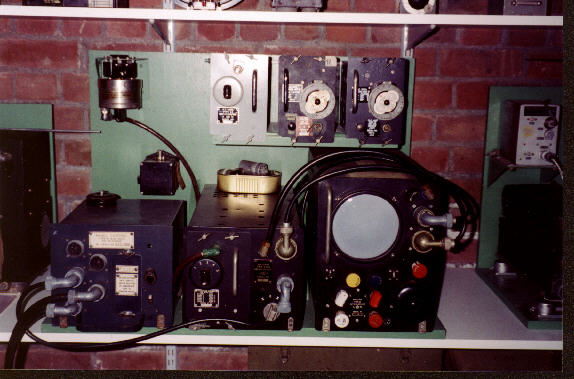
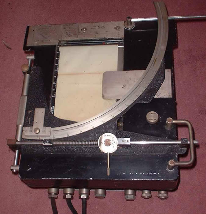
Gee receiver and display
DECCA System (QM)
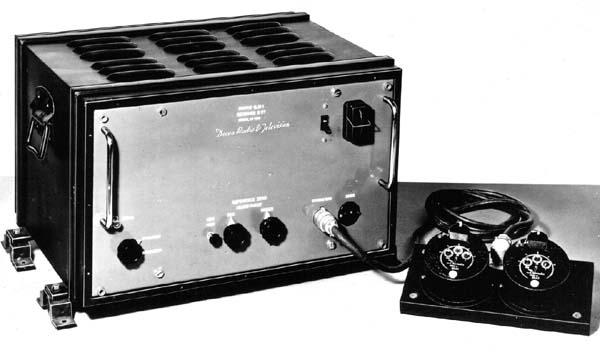
The Decca system (referred to as “QM” by the Royal Navy) was developed prior to D-Day and tested in secrecy to reduce the chance of it being jammed on D-Day.
For D-day, 30 units were hand built, Medusa and ML1383 were the only two HDMLs to have them fitted. It is believed that Medusa and ML1383 went out immediately prior to D-Day to test the system.
Special fine lattice charts covering the assault area were provided sealed for security. They were not to be opened before receipt of code message “OPEN ONWEST/O”.
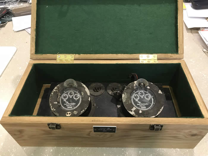
Of the original hand built units, we have the display dials from set number 19.
Medusa has a Mk4 Decca from 1960 on board.
The Decca system finally closed down in the UK in March 2000, however three final year students at Portsmouth University built a unit which receives GPS and converts it to Decca to drive the display.
We still have the charts so Medusa is now the only vessel in the world that can navigate by Decca!.
Decca QH system
Original QH dials
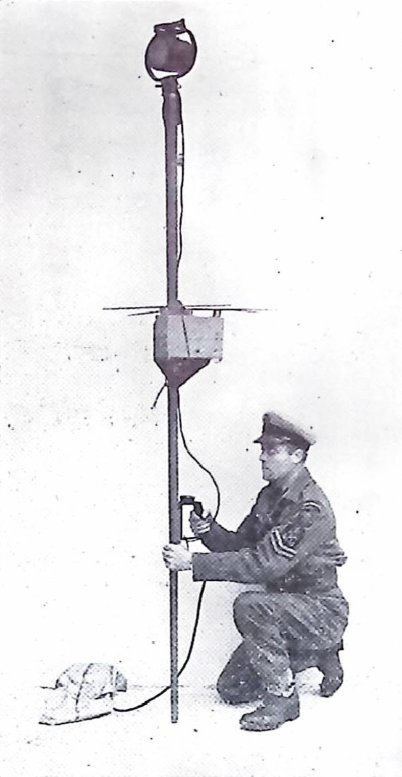
Radio Beacon 78T
There is very little published information on 78T but it is possible to put together a description from various snippets in reports.
78T was a radio beacon that transmitted on 214 MHz and would be picked up by 286 and 291 radars. It came as a self contained unit with its own battery and directional aerial and was positioned on medusa’s afterdeck.
This homing beacon was to be switched on when the beacon position was reached and transmitted on a bearing of 340 degs True. The directional aerial was kept on this bearing by a crew member. These transmissions continued until H Hour (13 hours being the approximate battery life of the device).
Type 78T transmissions could be picked up by Radar Types 286 and 291 fitted to some approaching units at 15 miles (if within the beam) or at less than 4 miles (outside the beam). The transmission was keyed to identify it, Medusa’s was keyed to give morse letter D.
The invasion force had their radar transmitters switched off to avoid detection by the Germans but kept receivers active to pick up the beacon.
Receivers are tuned to 214 MHz, and the radar display produced a string of needle-like pulses giving a code letter at approximate one minute intervals.
After action reports note some difficulty of distinguishing between beacons which suggests they were all on the same frequency so probably crystal controlled. To generate the HT voltage (circa 150V) from a lead acid battery they would probably have used a dynamotor (motor connected to dynamo) and this may also have driven the keying device.
78T pole mounted with aerial and signal lamp at top (pic courtesy COPP survey)
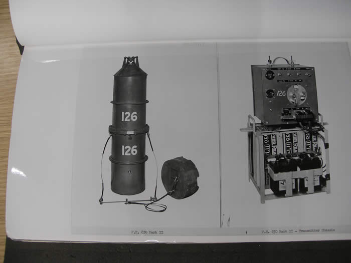
FH-830 Acoustic Beacon
These sea-bed acoustic beacons were laid by Fairmile B launches, ML 147, ML 151 and ML 198 on the 10 locations on the edge of the German minefield as Operation Enthrone.
Medusa’s was in position 50 05N, 000 46 44W and was activated by a timer in the beacon at D-1.
The Type 134 Asdic received the beacon transmissions allowing the boat to be conned into and maintained in position. HDML 1387’s beacon was set on High Tone with a four second repetition rate.
There is still a seabed obstruction in this position marked on the chart; no attempt would have been made to recover the units as they were fitted with a large explosive charge which would detonate if they were interfered with.
FH-830
Standard Equipment
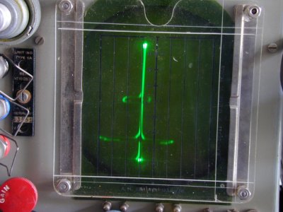
Radar, type 286/291
The naval type 291 radar was an adaptation of the RAF ASV radar fitted in Coastal Command aircraft for submarine spotting.
It was a metric wave device operating on approximately 214 MHz. The antennae were fixed yagi arrays on a topmast, later versions allowed a degree of training from a hand wheel in the radio room.
The display consisted of a single vertical line on the screen and targets would show as a horizontal deflection of the line, the further up, the greater the range.
It took some skill to operate but would detect surface targets at a few miles and aircraft at up to 20 miles.
Associated with the radar was an IFF transponder which allowed the radar to identify which targets were friendly and which enemy, similarly the equipment identified ML1387 as a friendly to other allied vessels and aircraft.
286/291 Radar
Type 134 ASDIC
The type 134 ASDIC consisted of a dome below the forward crew space, some electronics in the chart room and a paper chart display in the chart room on the forward starboard side.
The dome hung under the keel and projected up into the vessel through a bronze “stand pipe” which was fixed to the keel. Early versions just looked forward but later had the ability to train.
The display unit was a paper recorder with a mechanical device on top which would compute the correct time to drop depth charges.
The signal to drop was by pushing a large button which sounded a buzzer at which point one of the crew rolled a depth charge over the side.
Shortly after D day, Medusa’s ASDIC dome hit an underwater obstruction off the D day beached and flooded the forward part of the ship.
She made it back to Portsmouth in parlous condition where the ASDIC dome was dropped off and the hold plated over.
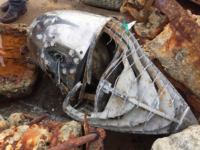
During dredging for HMS Queen Elizabeth, a type 134 dome was recovered.
Possibly Medusa’s, it is now in the National Museum of the Royal Navy.
Type 134 ASDIC display
Recovered ASDIC dome.
W/T Equipment
ML1387 carried a transmitter/receiver package type TW12C, manufactured by the Marconi company and based on a civilian system intended for small coasters and trawlers.
This would provide both morse and speech communication and ran off the vessels 24V DC system via a rotary converter.
The frequency coverage was 375-500KHz (morse) and 1200-3000 KHz (morse and speech) although later models covered up to 8820 KHz for increased range.
Transmitter TW12C
The transmitter used 3 valves, a type NT40 as an oscillator, a further NT40 as a modulator and an NT39 as an output amplifier.
The power output was 50W on CW (morse) and 30W on R/T (speech).
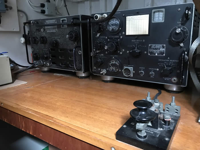
Receiver Type 384E
The receiver is a late 20s design and predates the Marconi CR100 set which was widely used. It consists of 4 valves, to ARS8 as RF amplifiers, an NR42 as a regenerative detector and an NR39 as an audio amplifier.
The Medusa Trust has an example of the 384 and would like to obtain a TW12 in order to refit the radio room.
Finding a transmitter seemed very unlikely and we found that by 1943, American TCS equipment was being fitted so we have put TCS in the wireless office. This has the aditional bonus that we can make it work.